Skip to Content

category

Category: Hoektronics

post

First to File? Nah, First to Blog!

As much as I dislike patents and the culture of intellectual property, the cold hard fact is that patents are real and they are here to stay. Now, there are a few ways to handle this – one is to completely ignore them and do what you want anyway. Another way is to use the system to defeat itself. Now, the patent system has the concept of prior art built into it. I’m not a lawyer but my understanding is that the minimum requirement for creating prior art is to publicly publish it. There is probably more beyond that to make it more visible, and if anyone has suggestions on an easy way of accomplishing that, please let me know!

Like most people out there, I sometimes have more ideas than time to implement them. So instead of keeping those ideas locked in a notebook somewhere unaccessible and not serving a purpose, I’m going to release them into the world as public domain in the hope that they might inspire, or at a very minimum keep an idea from being patented. I’m not claiming that these ideas are good, or that they are even new. Heck, some of them might even be patented already. They are just ideas in my head that it’s about damn time I put down on (digital) paper. Feel free to discuss, critique, or offer suggestions that expand on these ideas in the comments.

You can do whatever you like with these ideas, except for attempting to patent them yourself. It is my sincere hope that by releasing these ideas, more awesomeness and excellence will be brought into being. Furthermore, I hope that I might inspire others to similarly share their ideas to build a body of ‘protected’ ideas that are protected not by ownership, but by virtue of specifically being released into the public domain for use by anyone. The internet has shown us that the cost of sharing ideas is close to zero, whereas the benefits of collaboration are immense and very tangible. Why hoard your ideas like a jealous miser when it is impossible for a single human, or even a single corporation to act on every interesting idea that it generates?

Idea 1: 3 Point Planar Bed Leveling for 3D Printer or Other Digital Fabrication Device.

One of the biggest problems with 3D printing is keeping the build surface plane aligned with respect to the XY axes plane. Most printers implement this with a bed on adjustable springs. My idea is to add 3 buttons to the edges of the build platform. After the printer has homed to a known position, it moves to trigger each button with the extruder nozzle. The z-height of each triggered button is recorded, and the plane of the build surface can be calculated. During printing, the Z axis position is automatically adjusted to compensate for the build surface. Since most build surfaces use a PCB based heater, it should be trivial to add buttons in the appropriate places.

Idea 2: Adaptive Digital Fabrication with Camera Feedback

3D printing, CNC, lasercutting, and many other digital fabrication techniques are based on a 2D or 3D file format. Most machines simply follow the instructions and produce an object based on a static toolpath. It is possible to add a camera for visual feedback of the process and adapt the parameters of the 3D print dynamically. For example, one could detect if a print is failed, or measure if the initial height of a layer is too high or too low. One could even measure in realtime the extrusion width of a current layer and compensate by increasing or decreasing the amount of plastic extruded. With subtractive processes, one could even scan the base material and automatically determine where to cut the next parts from, freeing the user from panelizing / combining multiple jobs into a single sheet.

Idea 3: Combined CNC + 3D Printing for High Precision Layers

Extrusion based 3D printing is an excellent technology for its ability to create arbitrary geometric shapes of a high complexity. Unfortunately its resolution is not the best, and there are frequently defects on the outside of parts from layer misalignment, warping of the plastic, or other problems. CNC machining on the other hand is a very precise method of fabrication but the type of geometry that can be produced is much more limited. It is possible to combine them into a hybrid process where each layer is extruded, and then a very fine CNC end mill is run along the outside of the layer to trim the material to the exact dimensions desired. This might result in a nicer surface finish, as well as giving higher precision to the part.

Idea 4: Encoder Wheel on Filament Input to Detect Jamming or Stripping

Jamming and stripping of filament is probably the most common failure mode for a 3D printer. Adding an encoder wheel to the filament input will allow the software to check the expected movement of the filament to the actual movement of the filament. If they do not match, then there is likely an error and the machine can pause or go into an error mode. Furthermore, the machine can easily keep track of the amount of filament consumed and pause the job when the end of the filament spool has been reached.

Idea 5: Ultrasonic Welding of Microfilaments

Ultrasonic welding is a technology widely used in the manufacturing industry to weld plastic (and sometimes metals) together. It might be possible to adapt this technology to weld microfilaments together. If so, a printer could be designed that uses a miniaturized ultrasonic welder and a microfilament dispenser to build a 3D printer. Such a printer would have resolution based on the microfilament diameter. If welding of a metal like aluminum wire is possible, layer heights of less than 100 microns might be possible. Furthermore, a metallic microfilament combined with a plastic/non-conductive filament and a pick and place machine could be used to print housings, place parts, and directly wire electronics in the same job.

Idea 6: Pick and Place with Built-In Heated Build Platform

A pick and place machine with an integrated heated bed would allow a PCB to have components placed and then reflowed in a single operation. Such a system would not be good for high volume manufacturing, but could potentially be nice for low-volume prototyping operation.

Idea 7: Flexible Manufacturing Cell with Robot Arm + 3D Printer, CNC, Laser Cutter, Pick and Place Machine or other Digital Fabrication Devices

Digital fabrication machines are great, but it takes human intervention to clear finished jobs, assemble the parts together, and load new material. For 100% automation, a robot arm could be added to handle these tasks. It would require some sort of vision system and communication between each of the devices. The advantage would be having a higher level of automation that could allow higher level parts or even assemblies to be produced without human intervention. This is basically a prerequisite for high level fully automated manufacturing, and it seems obvious that combining purpose built equipment such as 3D printers or pick and place machines with a generic piece of hardware like a robot arm can allow products to be automatically produced using parts from each different machine.

Idea 8: CNC or Laser Cutter with Automated Sheet Loading

A very common method of production with a CNC machine or laser cutter is to cut flat sheets of material such as Acrylic, ABS, or POM. Adding an automated sheet feeder to the machine could allow a machine to operate nearly continuously by ejecting a finished sheet and then immediately loading the next sheet for processing. Software would likely be required to add tabs to hold the cut pieces in place during the unloading process that would be removed by the operator afterwards to break the piece out of the sheet.

Idea 9: EDM Cutting of Nozzles into Special Shapes

This idea is credited to Nicholas Starno. Using Electro Discharge Milling, it might be possible to create nozzles for a 3D printer with custom shapes such as a square. The benefit of a square nozzle would be that the extruded filament would have a square profile. When stacked up layer on layer, square filament would have a smoother surface than a stackup of rounded filament. Nozzles made via EDM milling might also have a better surface finish, as well as giving a much greater freedom in design choices for the geometry of the nozzle body itself.

Idea 10: Flippers to Eject Parts From a 3D Printer

The majority of 3D printers are incapable of continuous operation because they do not have a way to eject the part after a build has been completed. One potential option is to add one or more arms attached to a motor that would eject the part from the machine after it has been completed. Modern build platform surfaces such as polyimide, glass, and carbon fiber allow a print to stick to the platform when it is hot, but after it is cooled down the part can be detached very easily. The mechanical requirements for a system like this could be very low. It is likely that a simple DC servo gearmotor such as those used in RC cars or small robots would be a suitable, cheap, and simple to implement method to achieve this.
post

Industrial PID Temperature Controller Teardown

+ PID Temperature Controller Teardown

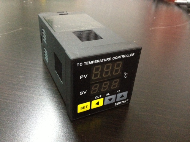
Last weekend, I went to the Guangzhou markets with my buddy Matt. There was lots of good stuff there, but one of the things that caught my eye were these PID temperature controller modules. Its the sort of industrial process control gear that is normally inaccessible to mortals. Fortunately for me, this was China, so I plunked down 80yuan and took one home with me.

photo (16)

+ Exterior

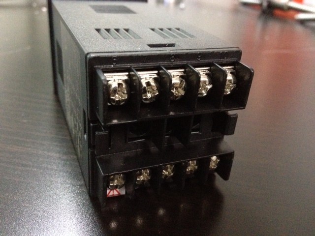
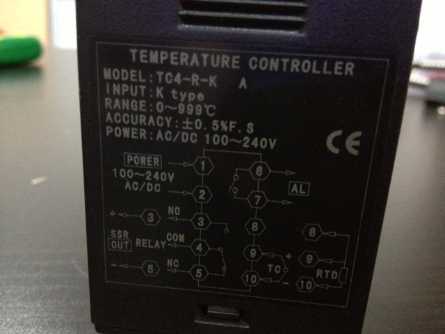
The unit is an elongated cube with interface on one side and terminals on the other. Its got a schematic silkscreened on one side to make hooking it up possible without a reference manual. Pretty snazzy.

photo (22)

+ Interior

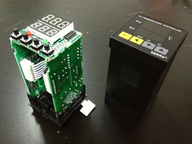
Getting inside was pretty easy. The thing has tabs that you press and all the guts slide right out.

photo (20)

The first thing I noticed was that the interior is pretty much all PCB. There are 3 PCBs + the terminal block that are all soldered together for electrical and mechanical strength.

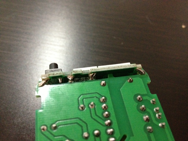
Elsewhere there 2 PCBs connecting. They designed pads onto each PCB where they needed to connect. Then someone simply bridged the pads with solder. Very clever. Not the strongest connection in the world, but it is certainly cheap and effective.

photo (19)

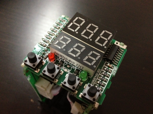
The interface board is interesting. Nothing too fancy here. A couple buttons, some LEDs, and some 7-segment displays. Nice and simple.

photo (21)

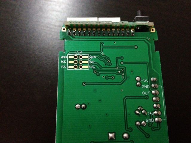
The board appears to be controlled by an Atmega and they kindly left the ICSP header exposed and labeled. Probably for their manufacturing process, but if I wanted to hack this device I could load my own firmware too.

photo (18)

+ Wiring it up

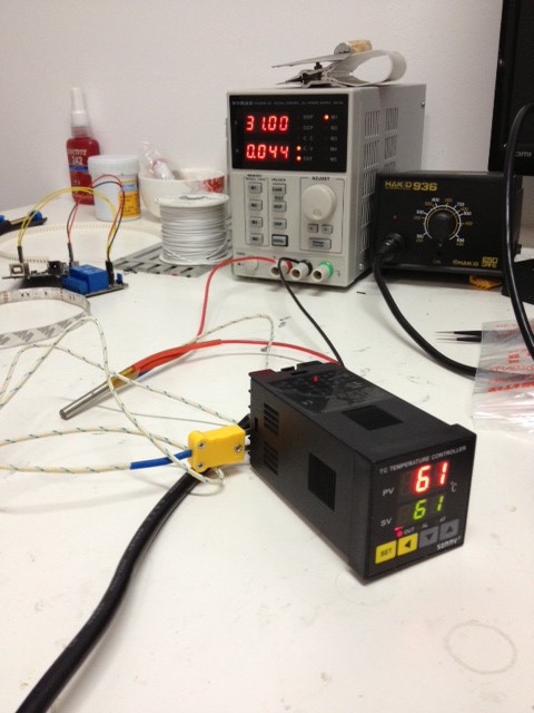
The controller is powered with AC wall current (110-230v) so I hacked up a power cable to control it. I took a thermocouple and a heater cartridge and taped them together with Kapton. I wired up my desktop bench supply to provide current to the heater.

photo (23)

Unfortunately my PID settings were way off and this thing has too many options that I didn’t want to mess with. After a couple minutes though it settled in an the appropriate temperature.

photo (17)

post

Challenges of Building a CNC Stepper Driver

I’m fascinated by motor drivers, and stepper motors in particular. There is just something so awesome about a modular little unit that will allow you to control a motor. As the motors get bigger, the awesomeness increases.

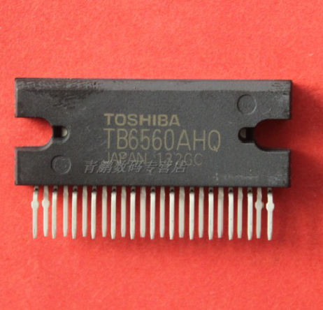
Lately I’ve been looking at high powered driver chips as part of a plan to build a CNC machine. Toshiba makes some great chips. The TB6560 is the ‘classic’ driver chip they make: 1/16th step, 4amps, and >30 volts. Unfortunately it has some flaws with power sequencing that causes it to blow up if you don’t turn VCC on before VMOT.

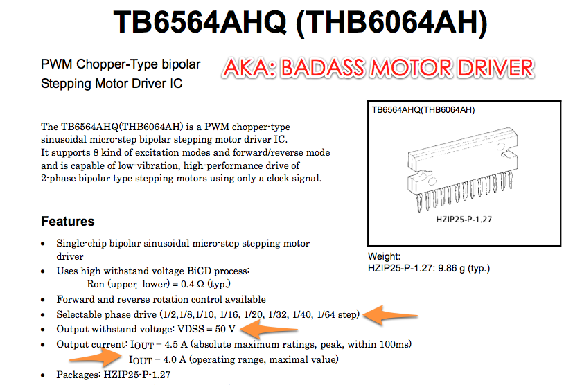
They’ve since released a few new driver chips. I designed a board around the beefy THB6064AH. This chip is pretty badass as its a 4.5A, 1/64th step, 50V beast. This thing will do some damage with the right motor. Unfortunately I’ve been struggling with the design. You can find it on Github.

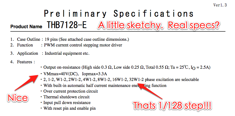
Lately I’ve discovered an even more awesome chip! The THB7128. Not only is it cheaper than the THB6064AH, but it does 1/128th stepping. The internet doesn’t have a ton of info. This appears to be a new chip on the market. This should make for extremely smooth operation. The only real downside is that it maxes out at 3A instead of 4.5A. Most of my motors are <3A so that shouldn't be a problem. I've ordered a demo board to test it out.

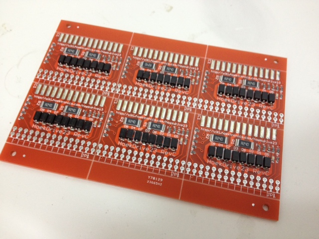
With my new design in hand, I ordered the boards + a new test fixture and got cracking. I used my Stencil8 setup to make 6 beautiful prototypes and a test fixture to go with it. Then things started to go wrong.

The Ugly Details of How I Messed Up

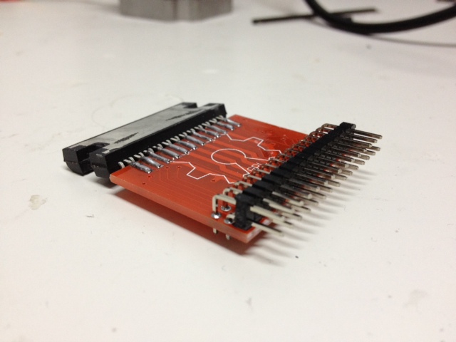
First, I messed up the connector on the test fixture. Basically it was mirrored, so I had to solder on the headers on the back side. That just generally made things awkward. Always do a reality check before purchasing boards!!!! Your printer and some cardboard (or old pcbs) are your friends.

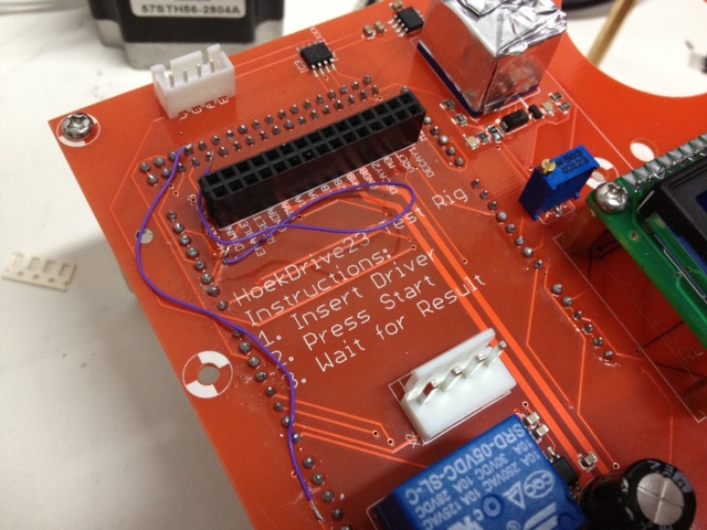
Second, I messed up a couple traces on the PCB. Nothing major, but things like the relay enable lines for 5V and VMOT being the same weren’t cool. Easy enough to fix with some jumper wires. The good news is the relays fired up first try, and the current measuring works as expected. I’ll do a writeup of this new and improved test fixture soon.

Third, and here’s where the trouble really started: I had no idea how to design for these higher power drivers. I knew about the sense resistors, and what value to make… but not what wattage. I knew they needed fast response diodes, but nothing more than that.

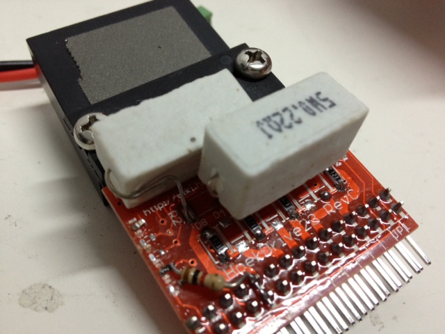
One very real problem I had was using too small of resistors. I never really quite grokked how to select current sense resistors for stepper motor drivers that need them. It’s actually very simple! Your driver is rated for a given current (say 4 amps). The datasheet will typically recommend a resistor value, as well as a formula for current based on a VREF. From that, it is easy to determine the ohm rating of your resistor (for the THB6064AH, its 0.22ohm). What they don’t say (and this is probably obvious to a real electrical engineer) is that the WATTAGE of the resistor can be calculated by W = I^2*R. In this case, 4*4*.22 = 3.2W. That pretty much rules out SMT resistors like I was using. Instead, you’ll need to use ceramic resistor. These resistors come in different sizes, but 5W is probably a safe bet. The next lowest is 3W which is less than the max required wattacge.

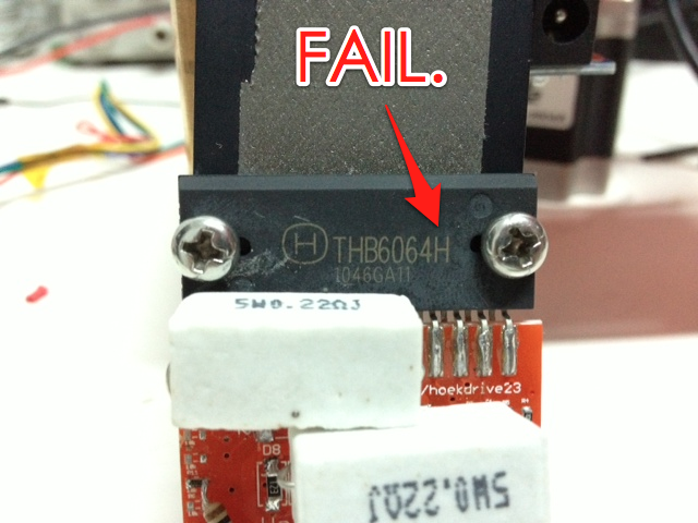
Fourth, and this is the main problem that I bashed my head into for 2 days in a row: The THB6064H is NOT THE SAME as the THB6064AH. I somehow purchased the THB6064H chips while designing for the THb6064AH. Of course this results in completely unpredictable operation that was so tantalizingly close that I *just knew* it had to be something in my circuit. Turns out, it was just me being an idiot.

Ultimately, this was a very frustrating but enlightening problem. I bashed my head at almost every single problem – both perceived and real. I did find some real issues, but the ultimate problem was one that I had completely overlooked. In the process I used the scope on just about every single pin, verified the test fixture, and just generally went over it with a fine toothed comb. I also learned a ton about the workings of the diode bridge, the current sense resistors, the resistors that control the oscillator, etc. I wish I had gotten it in one, but hey… thats life!

post

Stepper Motor Driver Test Fixture Design

These days I’m spending my time exploring the manufacturing landscape of Shenzhen in preparation for HAXLR8R 2013, future hardware startups, and just to grow my skills in general.

Motor drivers have been an ongoing passion in my life for a number of years, and I have a new design I’ve been working on based on the venerable Pololu driver. I’m getting 50 prototypes made by a local pcb assembly shop and I want to make sure they deliver quality prototypes. To that end, I’ve designed a test fixture to verify each board.

This sort of test is called a functional test, because it tests the actual functioning of the board as if it were being used in its intended application. For a motor driver, that means driving a motor and verifying that it did that correctly.

Design Goals

Here are a few of my design goals with the fixture:

  • Fully test each board in a simple and automated fashion.
  • Make the test fixture easy to use and easy to understand.
  • Document it so that others can learn from and expand on my work.
  • Release it open source (BSD) so others can use it to make better things.

Designing a test fixture is much different from designing a board for mass production. With a test fixture, I’m really not worried about component cost, PCB size, component density, certification, or any of those other worries that go into making electronics on a large scale.

Instead, what I care about is building a nice, reliable board that allows me to ensure the board I’m testing is doing what I expect it to be doing. The very first step towards achieving that is the spec! Realistically, you should write your spec before you even design the board you’re going to test. Of course this rarely happens in the real world, and the spec often changes during development as you come to better understand the nature of the components and the board you’re designing.

Test Specifications

At a minimum, your spec should have a listing of testable requirements. In the world of software, this are basically your unit test requirements. In electronics, you have things like current draw, voltage levels, etc. You probably also have application specific requirements that may require specialized sensors. In my case, I want to test a motor driver so I’m using a rotary encoder to record the exact movement generated by the motor. My spec looks something like this:

  • 1 rotation / Mode: full step / Direction: forward
  • 1 rotation / Mode: full step / Direction: reverse
  • 1 rotation / Mode: 1/2 step / Direction: forward
  • 1 rotation / Mode: 1/2 step / Direction: reverse
  • 1 rotation / Mode: 1/4 step / Direction: forward
  • 1 rotation / Mode: 1/4 step / Direction: reverse
  • 1 rotation / Mode: 1/16 step / Direction: forward
  • 1 rotation / Mode: 1/16 step / Direction: reverse

Test Fixture Controller

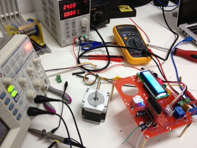
At the highest level, your test fixture has 4 states: idle, testing, pass, and fail. I am using 3 LEDs to indicate each state: yellow = testing, green = pass, and red = fail. I also have a 16×2 character LCD to provide more detailed feedback on sub-test status.

In order to drive all this, you need some sort of brains. I naturally went with the trusty and venerable Arduino MEGA. I could have used the smaller Arduino, but I wanted something that had pins to spare should I need them. Cost isn’t a huge consideration when designing a test fixture, so I wasn’t worried about overkill. Doing this the easy and fast way was a major consideration.

With my spec in hand, I fired up Eagle and started designing. The core of the fixture is pretty simple: an Arduino MEGA, 3 LEDs, a button to start the test, and some mounting holes. These are the core of the test fixture, and if you’d like to make your own, the design files are up on Github for your modification pleasure.

Beyond the core functionality, I added the motor driver socket, motor connection header, and the encoder connection header. It really is a rather simple test fixture.

The Arduino software is very straight forward: execute each test, display the right information at the right time, and light up the right LEDS. It also outputs extra data to the serial port which I could theoretically collect if I was going to do this on a massive scale and wanted to aggregate test result data. The software is also up on Github if you’re interested in seeing how it works.

The End Result

Once the board was designed, I soldered up the first prototype. Obviously it didn’t completely work. 😉 One major flaw was not connecting the VCC and GND for the LCD backlight. A couple jumper wires later and it was working like a charm.

Once I got it working, my main goal was to have a smooth and fast test sequence. For me that means each board should finish testing in under 10 seconds. It also means that it should be clear and easy to use. I believe I achieved that quite well, and if you watch the video you can see the test fixture in operation.

Making it tidy

After building the test fixture, I realized it needed some sort of enclosure or structure. There are a couple ways to go about this. The first thing that crossed my mind was to use a custom laser-cut enclosure. It would look sweet and protect my new test fixture. However, I didn’t want to wait for my laser cutter supplier and I wanted something to keep it stable while I was working. Inspiration struck when I realized that I already had a very nice, digitally fabricated structure pre-made… the PCB itself!

When you do a prototype run of a PCB, you typically get more than one. In this case, I got 12 PCBs even though I ordered the minimum number possible. I’m certainly not going to use all those PCBs, so I thought why not use them for the structure. Since the holes on the PCBs are exactly the same, all I had to do was add some standoffs between the PCBS and I had a nice, sturdy open-box frame that will probably stand up to moderate use.

Areas for improvement

All in all, I’m pretty happy with how this test fixture turned out. I used it to test my hand-made prototype boards, and it passed the working ones while failing the broken ones. I consider that in and of itself to be a success. However, this test fixture is very simple and there is lots of room for improvement! When I do a Rev B, here are some of the things I’d like to do:

  • Add current measurement to the VCC and VMOTOR power supplies. I want to know how much current is being drawn at various points during operation. For example when the board first starts up, I would like to be able to detect a short and turn it off. I would likely use something like the ACS712 chip.
  • Add relays to VCC and VMOTOR supplies. In combination with the current measurement chip, this would allow me to detect shorts. It would also build more safety into the device since plugging and unplugging the driver would happen with the power off.
  • Add a digipot to change the VREF settings. Right now this functionality is not begin tested, and its a pretty critical part of the board design. With the current measurement stuff added in, it should be pretty straightforward to verify it too.
  • Move the connectors to the bottom of the board to keep things tidy. I’d like all the wires to be on the inside of the test fixture if possible.
  • Move the stepper driver socket to the middle of the board. Right now it is a bit tucked away in with the other components. It makes routing a bit trickier, but it would really make it easier to use for the operator.
  • Move the 4th hole outside the Arduino. I made a mistake of putting one of the mounting holes over the Arduino. PCB space isn’t a huge premium, so I should have made the PCB bigger to accommodate it.
  • Use blue LED for “testing” mode. Just because it will look cooler. Also, the 10mm LED footprints I used have bad pin spacing. Oops.
  • I used through hole parts because I thought “Oh, I’m only doing 1 of these.” It turns out that makes things harder to source, especially since I really only have SMT components in my workshop. Thru-hole, not even once. =)
  • The board itself has one major flaw: it is not polarized! This means the board could be inserted backwards and damaged. This is a design flaw with the original Pololu design, and I haven’t yet figured out a way to route around it and still maintain compatibility. I’m not sure how to modify the test fixture to prevent this either. This will be solved the good old fashioned way: good instructions, operator training, and paying attention.

Open Source Hardware

In case you didn’t notice while reading the article, this board and software is 100% open source, under the BSD license. You can get it on Github. You’re welcome to use it in your own projects, and the BSD license means you don’t need to contribute back. This means you should have no problems using it in a corporate environment where you might want to keep your test fixtures secret. Why release it that way? Well, because I’m cool like that. 🙂

post

Super Simple SMT: Stencil8

Over the years, I’ve soldered a fair number of boards.  I’ve also seen how professional factories produce their boards.  This is my technique for doing it myself, and I hope it works as well for you as it does for me.  🙂

Note: the files needed to make the fixture, custom pcb setup, and stencil are on Github – Stencil8.  This whole project is OSHW.

Required Tools Overview:

  1. PCB Fixture Block + Tooling Pins
  2. PCB w/ Tooling Holes
  3. Solder Paste Stencil
  4. Solder Paste + Squeegee
  5. Reflow Oven (or Hotplate)
  6. Isopropyl Alcohol (Rubbing alcohol.)

Process Overview:

  1. Set your tooling pins onto the appropriate grid points.
  2. Fit your PCB on the fixture.
  3. Place your solder stencil on the fixture.
  4. Use the Squeegee to apply solder paste to the stencil (and PCB).
  5. Gently remove the stencil from the figure.
  6. Use tweezers to place components on the appropriate pads.
  7. Reflow your PCB like normal using your reflow oven or hot plate.
  8. Solder your through-hole components (if any…)
  9. Test, test, test!

Key Component: Precision Tooling Fixture Block

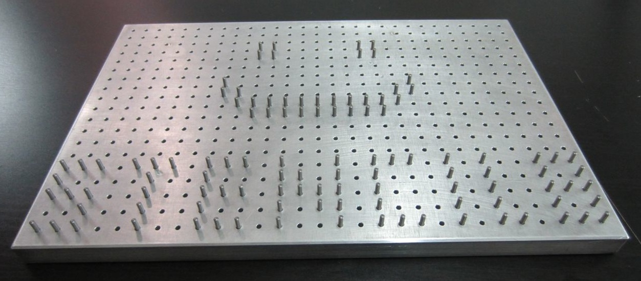
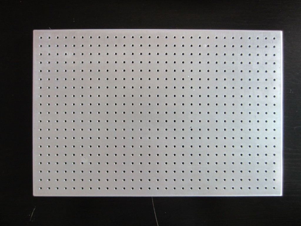
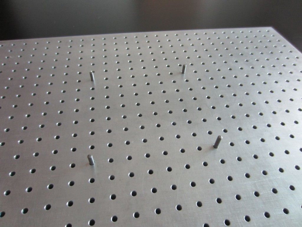
First up, The pcb fixture block is the base of the whole technique (literally).  It is a solid chunk of aluminum  with precisely spaced 10mm grid of 2.5mm holes.  These holes accept the 2.5mm tooling pins.  These pins are what ensure that your board and stencil line up exactly.  This precision is why this technique is so easy.  It is a permanent tool, and you’ll only ever need one of these.  Get a nice one, its worth it.  You can DIY based on the drawings, or have one custom CNCed.  I would highly recommend CNC.

Key Component: Solder paste stencil

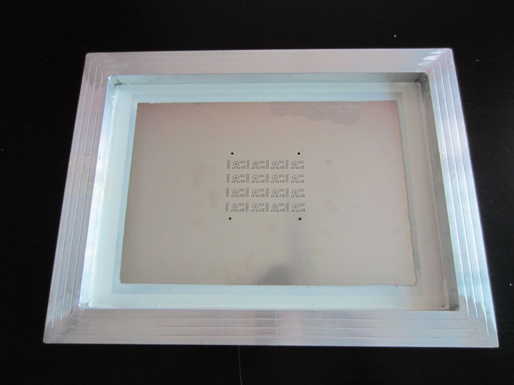
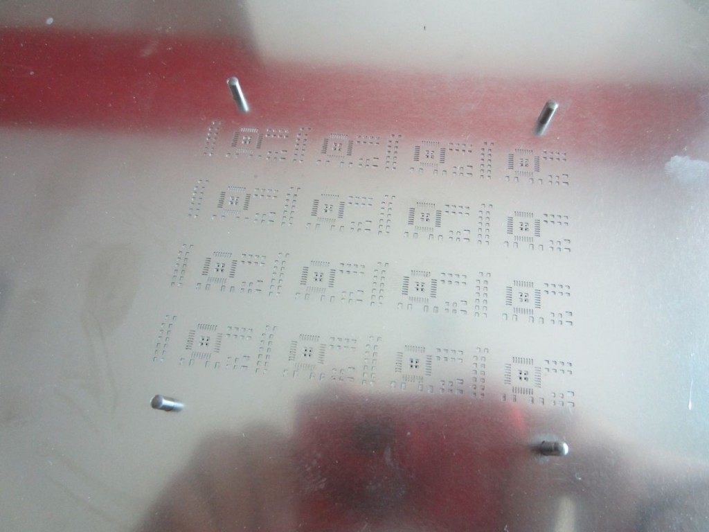
Next, the solder paste stencil.  This gorgeous digital craftwork is how you precisely control the amount and location of the solder onto your PCB.  It is a thin sheet of steel that has tiny openings etched in it with acid or lasers.  With this, you just glop on solder, and then scrape it off.  When you’re done, you have a masterfully applied set of solder for every SMT component on your board.  All you have to do is put things where they go.

Getting the solder stencil might be tricky.  I live in Shenzhen, where a stencil like this costs $20.  A google search for lasercut smt stencil shows that you can have it elsewhere, but its more expensive.  Making the stencil is very easy: you just send the Solder Paste GERBER layers to the stencil manufacturer.  In eagle these are the tCream and bCream layers respectively.  They correspond to the .GTP and .GBP GERBER files.

Key Component: PCB with Tooling Holes

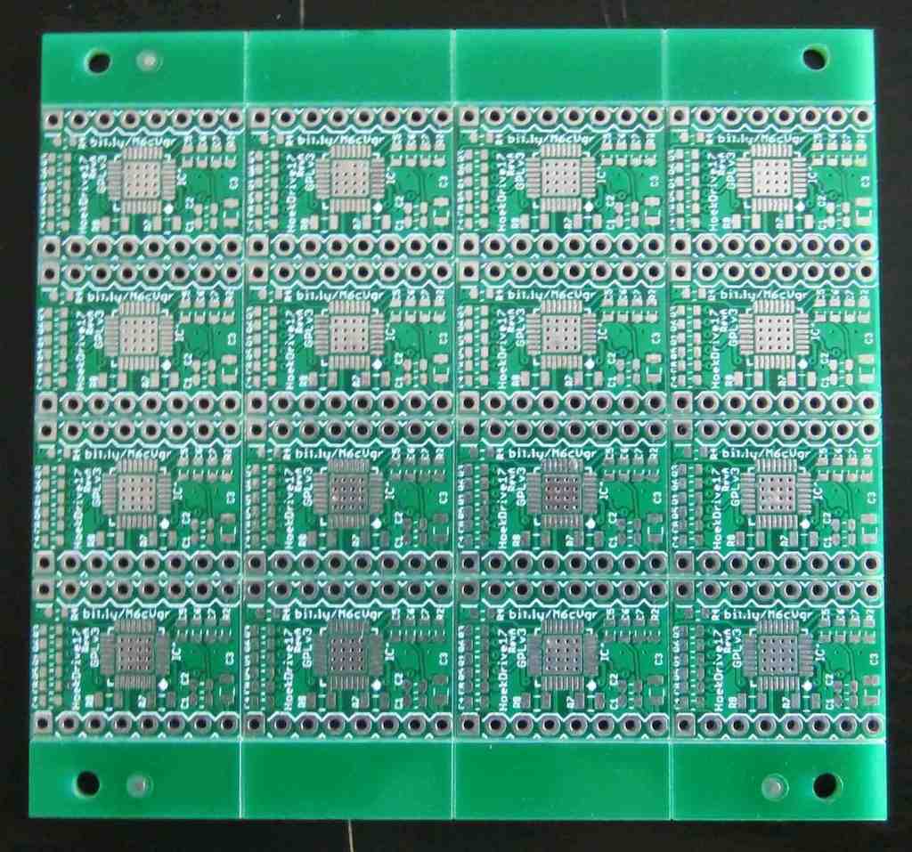
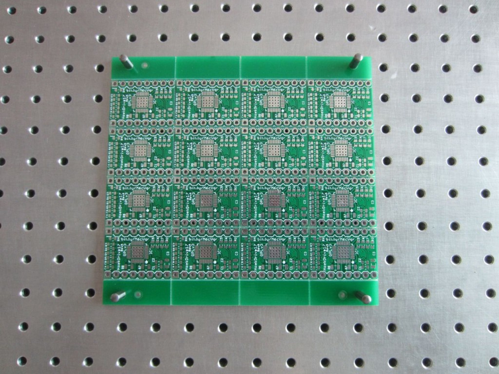
You have 2 options:  put tooling holes into your PCB directly or have your board panelized w/ tooling holes on the margins.  The latter allows you to do a large number of boards in a single application, which can be very nice in some situations.  It also doesn’t affect the design of your board at all.

If you opt to put tooling holes into your PCB, you will need to make sure there is a corresponding circular pad in the solder paste layers in your CAD.  This is because the solder paste stencil will need to have an opening there to fit the alignment pin.  You can find a part for this in my EAGLE library.

If you have an excellent PCB supplier, they can send you your boards in a panelized state.  This means you will get a single sheet of PCB that has all the boards + tooling holes.  The PCB is “V-cut” so that you can easily break it apart by flexing the board.  This is really awesome for doing small batches of boards.  The document I used to communicate this to my Chinese PCB fab is located on github.

Key Tools: Solder Paste + Squeegee

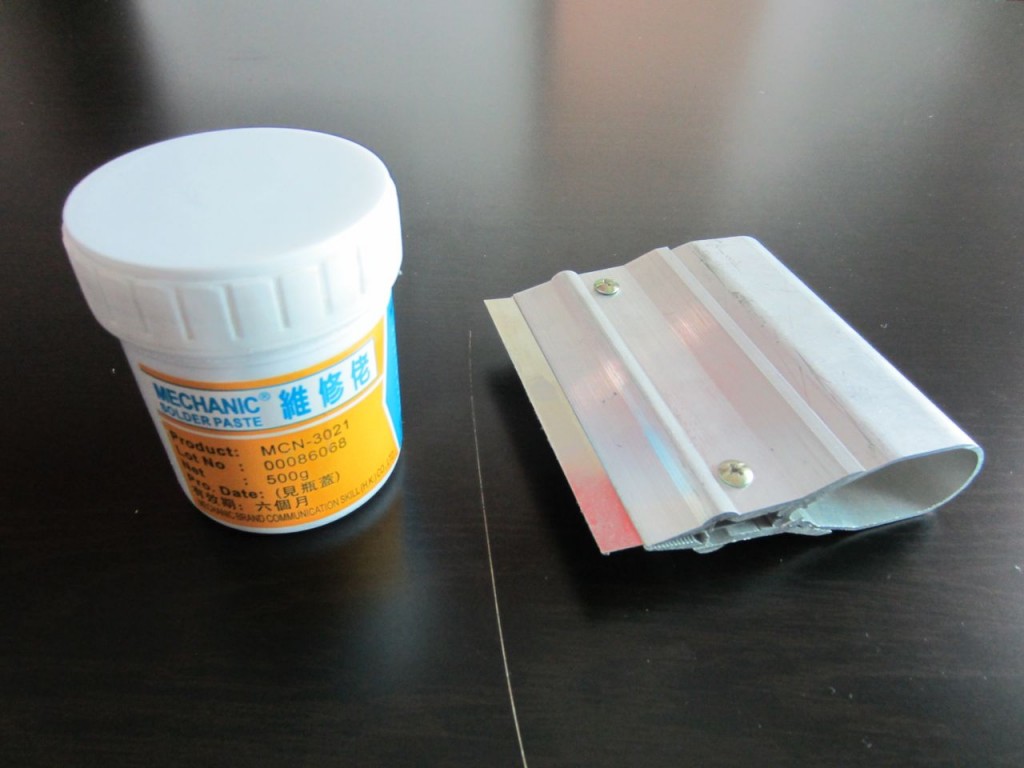
In order to use this process, you need solder paste and a squeegee.  The paste comes in tubs or tubes, although tubs are the most common.  Try and mix it up a bit first before applying.  You’ll want a squeegee with a metal blade in order to get the best application.

Key Tools: Reflow Oven

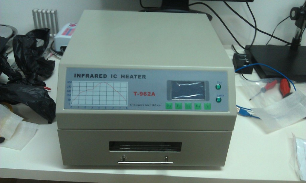
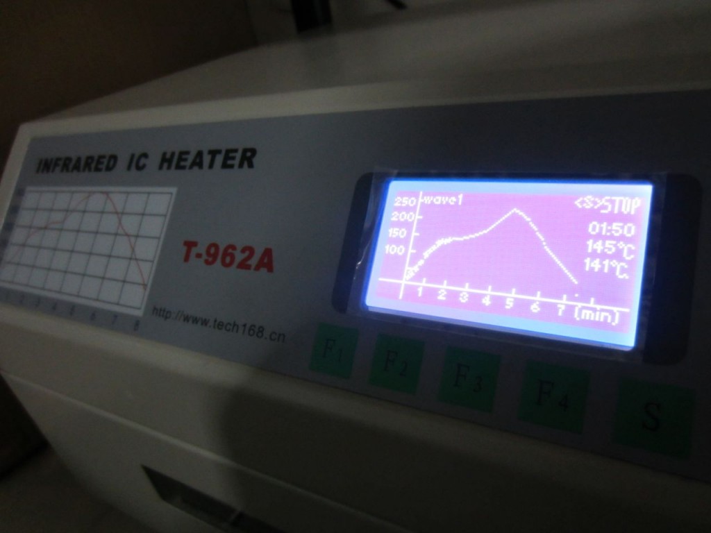
If you want to get fancy, use a reflow oven like this.  This oven has temperature profiles which means it gradually heats up and cools down your PCB for optimum soldering.  It’s also a nice “set it and forget it” type of process.  If you’re forgetful like me, this means you can pop in the PCB and come back in half and hour without burning anything down.

If you don’t want to splurge, there is always the hotplate method which can be done for very cheap.  Lots of tutorials out there.

Step 1: Set your tooling pins

The crux of this technique is using your precision tooling block + precision positioning pins to accurately align the PCB and the solder paste stencil.  This helps you get very high quality solder paste deposition exactly where you want it.  When you work with multiple boards, or when you work with very small parts it can be extremely difficult to align by hand.

Setting the pins is easy.  Put the pins in the right spot, and double check it using your PCB.  Technically you only need 2, but I’ve found that 4 gives you a nice, snug fit that helps with preventing misalignment.

Step 2: Fit your PCB on the fixture

Your PCB should fit over the tooling pins and lay flat against the tooling block.  If it doesn’t fit, try using 3 or 2 pins.  Snug is good, but don’t force it.

Step 3: Place your Solder Stencil on the tooling pins

Using the same tooling pins, place your solder stencil onto the tooling block.  Since the stencil is much bigger, it can be hard to get it aligned.  I like to line up one hole first using light from above, then rotate the stencil around that pin until it slides over the rest of the pins.  It should lay flat against the PCB when you are done.

The pins should align the PCB and solder paste stencil very precisely.  You should not see any green soldermask, only the silver pads where solder paste needs to be deposited.

Step 4: Apply your solder paste

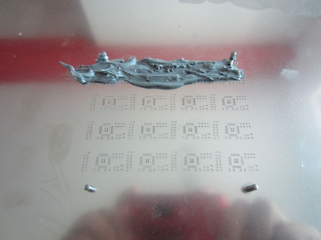
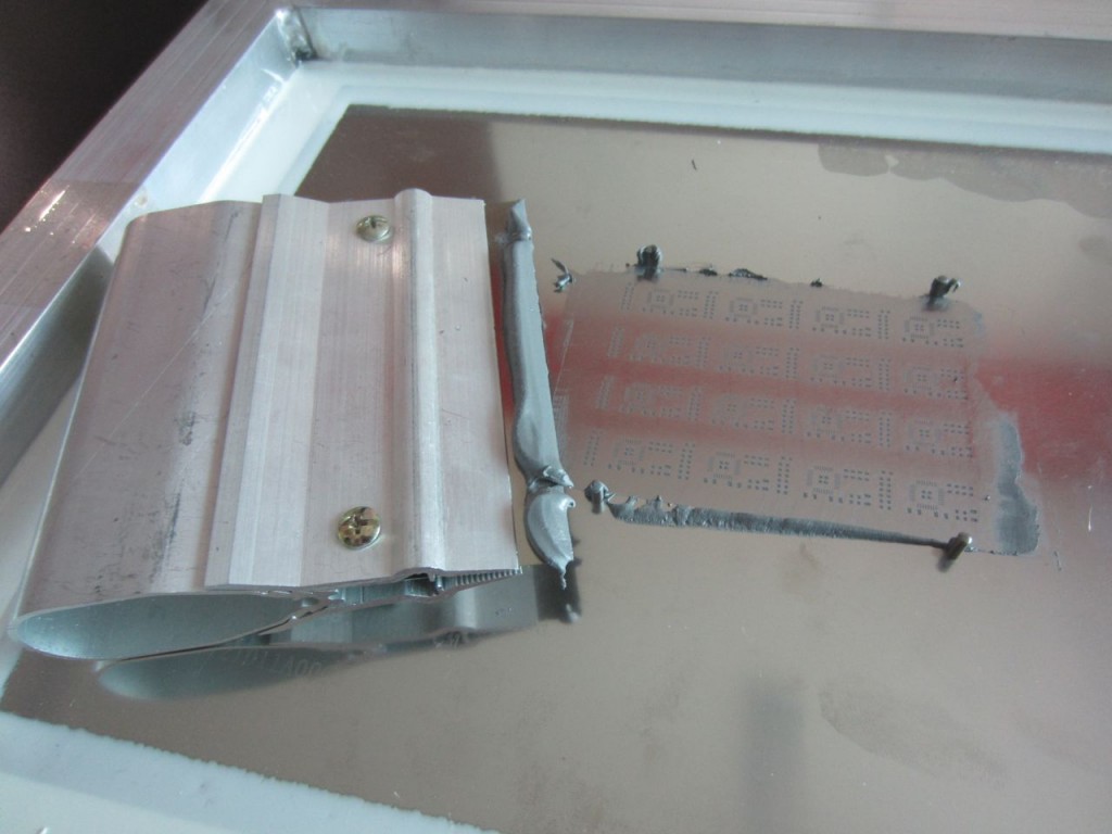
Applying the solder paste is easy and fast.  Place a dollop of solder paste onto the stencil.  Use your squeegee to apply it across the face of the stencil.  Angle the squeegee in the direction you’re moving it, and make sure to apply the paste both forwards and backwards to get every little nook and cranny filled.

Apply a dollop:

Squeegee it across:

Step 5: Gently remove the stencil from the fixture

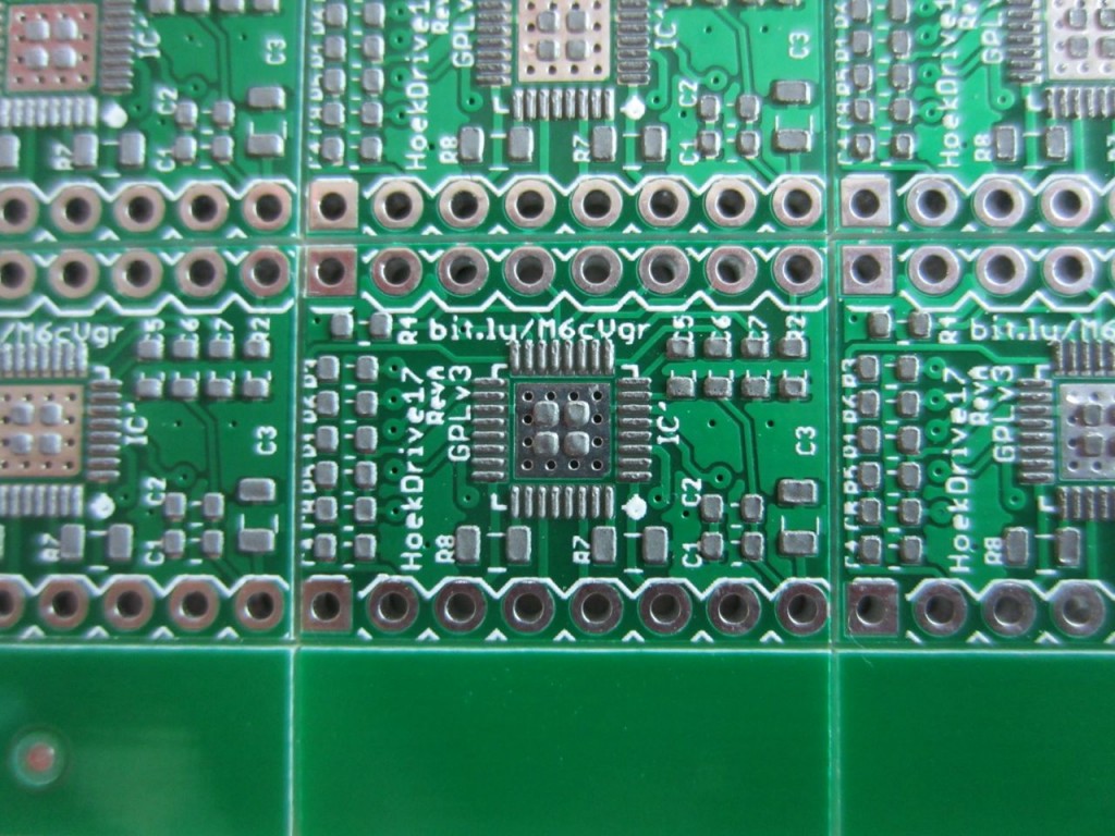
Once you’ve applied the solder paste, carefully remove your stencil.  You should immediately clean the stencil off with isopropyl (rubbing alcohol) so that you can use it again later.  You should end up with beautifully applied solder paste like the picture above. I highly recommend leaving the PCB on the fixture.  This will give you a stable base to work on, and will prevent you from knocking the PCB onto the floor or something like that.

Step 6: Place SMT components using tweezers

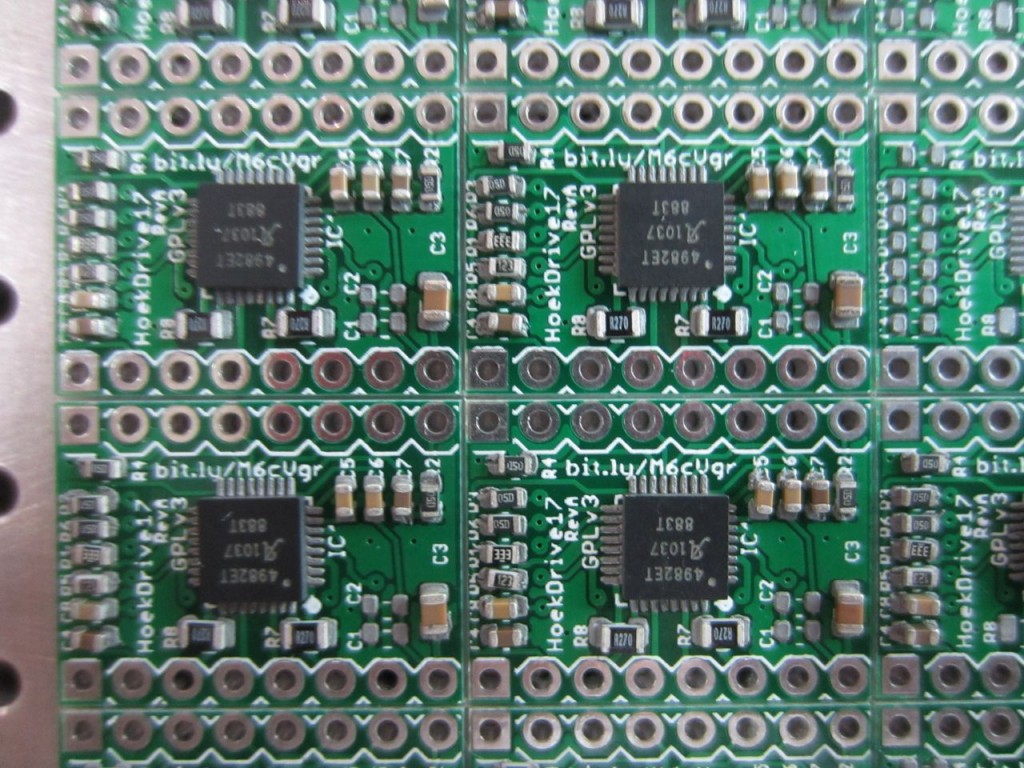
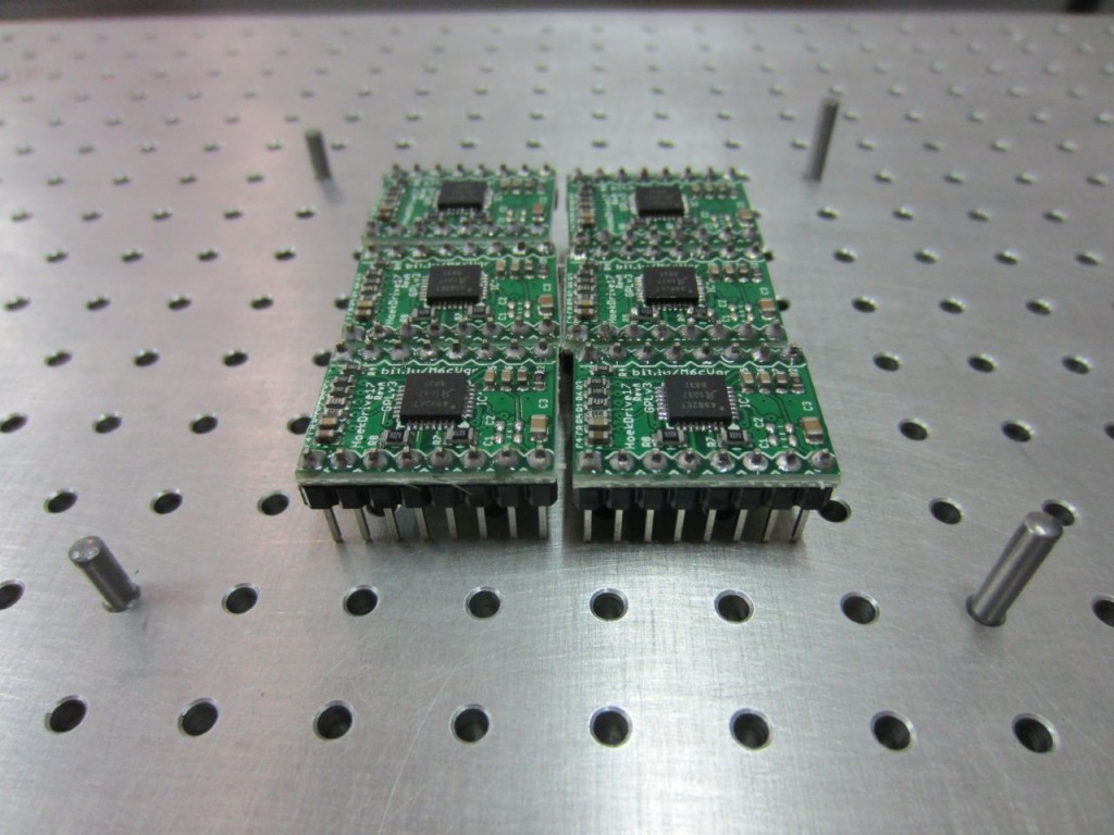
This is probably the trickiest part of the process.  Use tweezers to pick and place each component onto the appropriate spot.  A magnifying glass can help tremendously with this.  Make sure you have good lighting and that you know what components go where.  If you make a mistake you can dab a bit of solder on.  Also, when the solder melts, it will self-correct to a small degree, so its okay if components are not exactly aligned.  The boards in these pictures came out just fine, and you can see that the components are skewed a bit here and there.

Step 7: Reflow your board like usual

Use whatever process is convenient for you.  I’m in love with this SMT oven here, but you may have your own preferred technique.  If it works, go for it!  Once the board has been soldered, it is a good idea to remove the flux using isopropyl alcohol and a toothbrush.  Just don’t use it on your teeth afterwards!

Step 8: Solder your through-hole components (if any)

Using your trusty handheld soldering iron, solder in any through hole parts.  If your board doesn’t have through hole parts, obviously skip this step.

Step 9: Test, test test!

Before using your board straightaway, test it!  If you have a test fixture, then use that.  If not, it is good to test for shorts between power/ground, as well as using a benchtop supply in current limiting mode set to a very low value and slowly ramp up the allowed current draw.  If there is a short, this will allow you to catch it in a non-destructive way.

You’re done!

Using this technique you can solder very small parts that would otherwise be extremely difficult.  I’ve successfully soldered 0402 components and QFN components with a 0.5mm pitch.  You can easily do TQFP and any of the larger packages like 0603, 0805, and 1206.

If you have any feedback, leave it in the comments, or email me at zach at hoektronics dot com.  Enjoy!

post

Hoektronics – Coming soon.

There’s nothing to see here… yet.  This site is the future blog home for myself, Zach Hoeken.  You will find posts about projects I’m working on, boards I’ve designed, crazy things I’ve seen in China, and musings about life, open hardware, and all sorts of other stuff.