Over the years, I’ve soldered a fair number of boards. I’ve also seen how professional factories produce their boards. This is my technique for doing it myself, and I hope it works as well for you as it does for me. 🙂
Note: the files needed to make the fixture, custom pcb setup, and stencil are on Github – Stencil8. This whole project is OSHW.
Required Tools Overview:
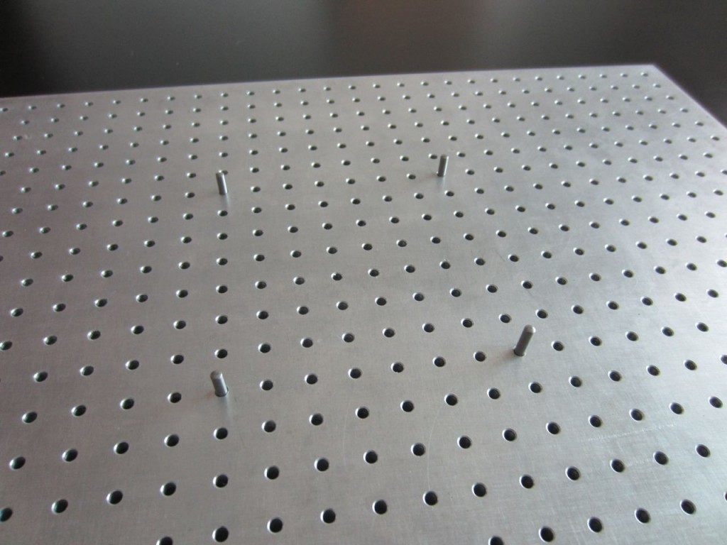
- PCB Fixture Block + Tooling Pins
- PCB w/ Tooling Holes
- Solder Paste Stencil
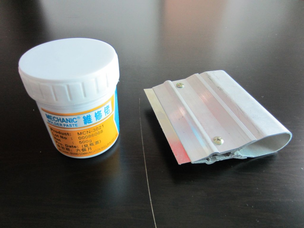
- Solder Paste + Squeegee
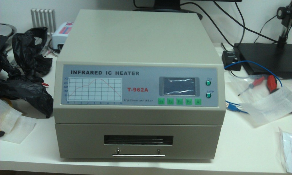
- Reflow Oven (or Hotplate)
- Isopropyl Alcohol (Rubbing alcohol.)
Process Overview:
- Set your tooling pins onto the appropriate grid points.
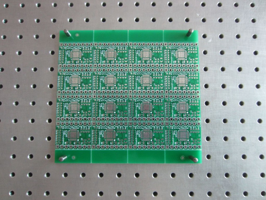
- Fit your PCB on the fixture.
- Place your solder stencil on the fixture.
- Use the Squeegee to apply solder paste to the stencil (and PCB).
- Gently remove the stencil from the figure.
- Use tweezers to place components on the appropriate pads.
- Reflow your PCB like normal using your reflow oven or hot plate.
- Solder your through-hole components (if any…)
- Test, test, test!
Key Component: Precision Tooling Fixture Block
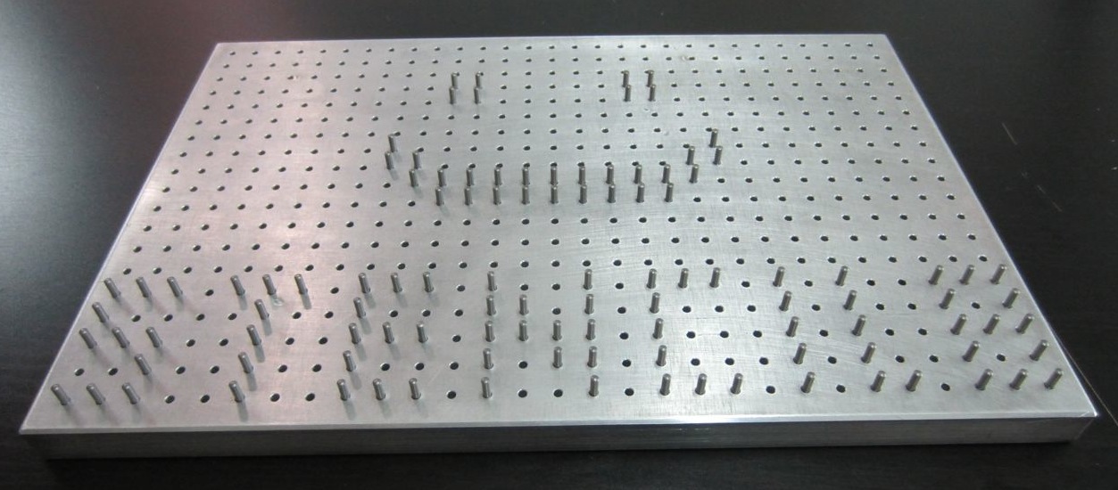
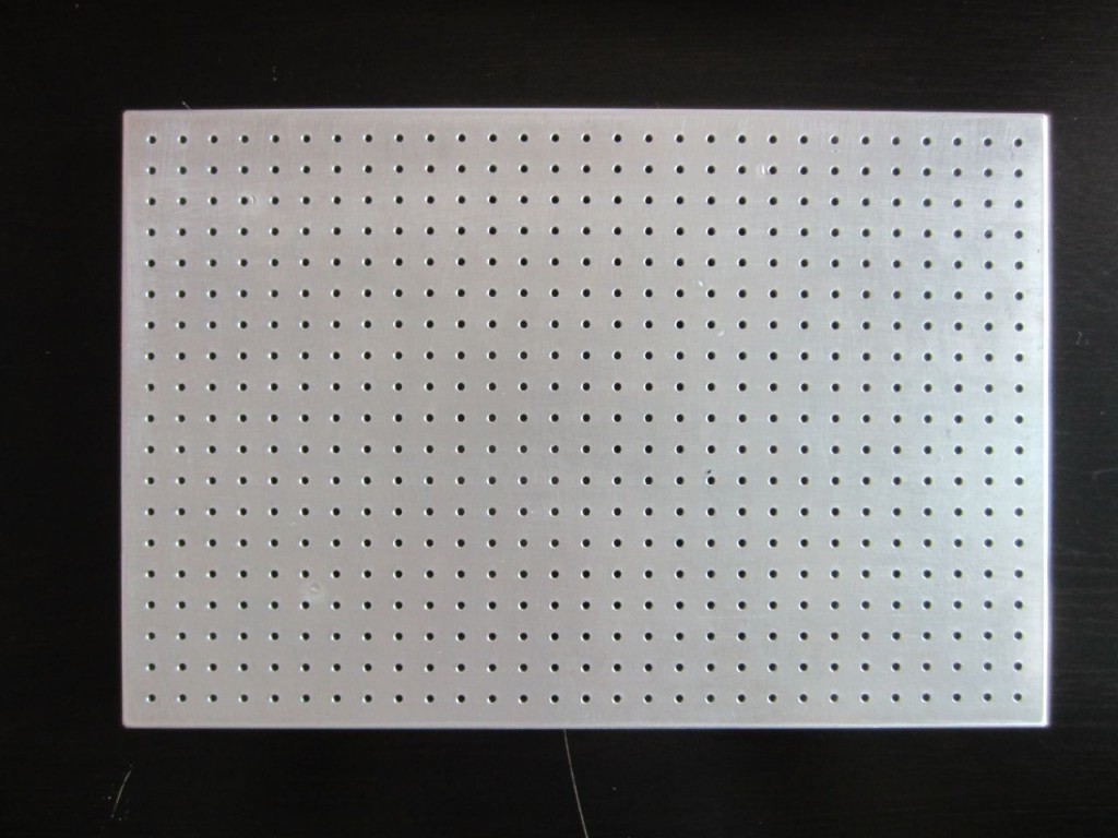
First up, The pcb fixture block is the base of the whole technique (literally). It is a solid chunk of aluminum with precisely spaced 10mm grid of 2.5mm holes. These holes accept the 2.5mm tooling pins. These pins are what ensure that your board and stencil line up exactly. This precision is why this technique is so easy. It is a permanent tool, and you’ll only ever need one of these. Get a nice one, its worth it. You can DIY based on the drawings, or have one custom CNCed. I would highly recommend CNC.
Key Component: Solder paste stencil
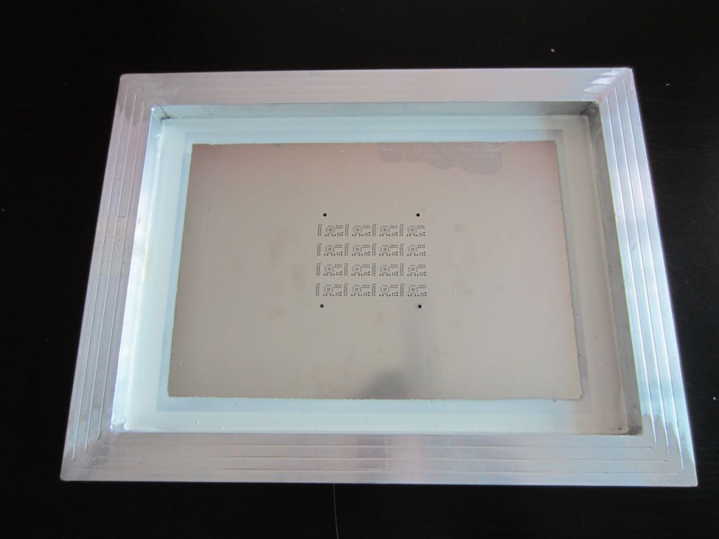
Next, the solder paste stencil. This gorgeous digital craftwork is how you precisely control the amount and location of the solder onto your PCB. It is a thin sheet of steel that has tiny openings etched in it with acid or lasers. With this, you just glop on solder, and then scrape it off. When you’re done, you have a masterfully applied set of solder for every SMT component on your board. All you have to do is put things where they go.
Getting the solder stencil might be tricky. I live in Shenzhen, where a stencil like this costs $20. A google search for lasercut smt stencil shows that you can have it elsewhere, but its more expensive. Making the stencil is very easy: you just send the Solder Paste GERBER layers to the stencil manufacturer. In eagle these are the tCream and bCream layers respectively. They correspond to the .GTP and .GBP GERBER files.
Key Component: PCB with Tooling Holes
You have 2 options: put tooling holes into your PCB directly or have your board panelized w/ tooling holes on the margins. The latter allows you to do a large number of boards in a single application, which can be very nice in some situations. It also doesn’t affect the design of your board at all.
If you opt to put tooling holes into your PCB, you will need to make sure there is a corresponding circular pad in the solder paste layers in your CAD. This is because the solder paste stencil will need to have an opening there to fit the alignment pin. You can find a part for this in my EAGLE library.
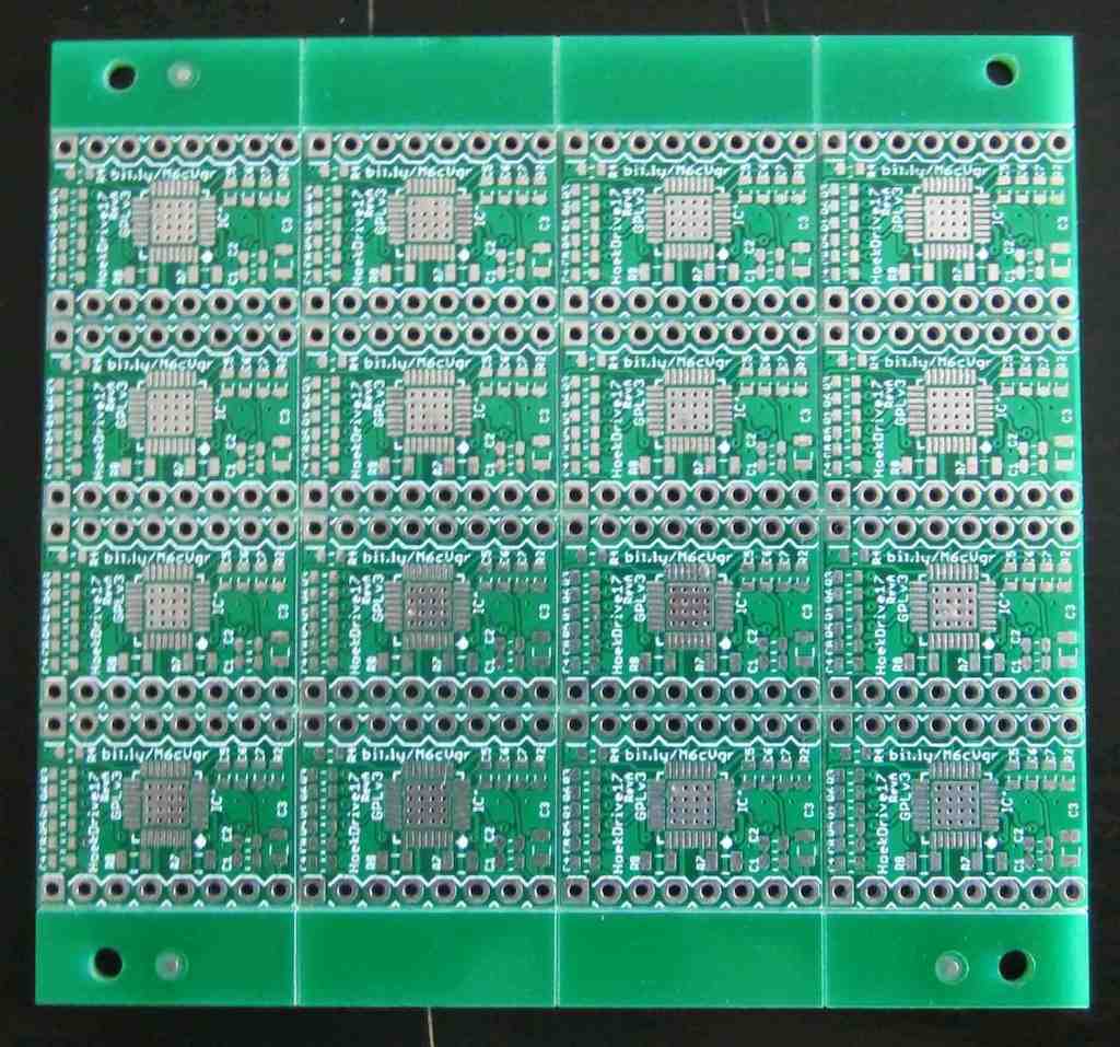
If you have an excellent PCB supplier, they can send you your boards in a panelized state. This means you will get a single sheet of PCB that has all the boards + tooling holes. The PCB is “V-cut” so that you can easily break it apart by flexing the board. This is really awesome for doing small batches of boards. The document I used to communicate this to my Chinese PCB fab is located on github.
Key Tools: Solder Paste + Squeegee
In order to use this process, you need solder paste and a squeegee. The paste comes in tubs or tubes, although tubs are the most common. Try and mix it up a bit first before applying. You’ll want a squeegee with a metal blade in order to get the best application.
Key Tools: Reflow Oven
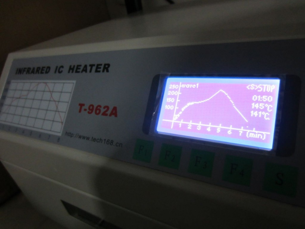
If you want to get fancy, use a reflow oven like this. This oven has temperature profiles which means it gradually heats up and cools down your PCB for optimum soldering. It’s also a nice “set it and forget it” type of process. If you’re forgetful like me, this means you can pop in the PCB and come back in half and hour without burning anything down.
If you don’t want to splurge, there is always the hotplate method which can be done for very cheap. Lots of tutorials out there.
Step 1: Set your tooling pins
The crux of this technique is using your precision tooling block + precision positioning pins to accurately align the PCB and the solder paste stencil. This helps you get very high quality solder paste deposition exactly where you want it. When you work with multiple boards, or when you work with very small parts it can be extremely difficult to align by hand.
Setting the pins is easy. Put the pins in the right spot, and double check it using your PCB. Technically you only need 2, but I’ve found that 4 gives you a nice, snug fit that helps with preventing misalignment.
Step 2: Fit your PCB on the fixture
Your PCB should fit over the tooling pins and lay flat against the tooling block. If it doesn’t fit, try using 3 or 2 pins. Snug is good, but don’t force it.
Step 3: Place your Solder Stencil on the tooling pins
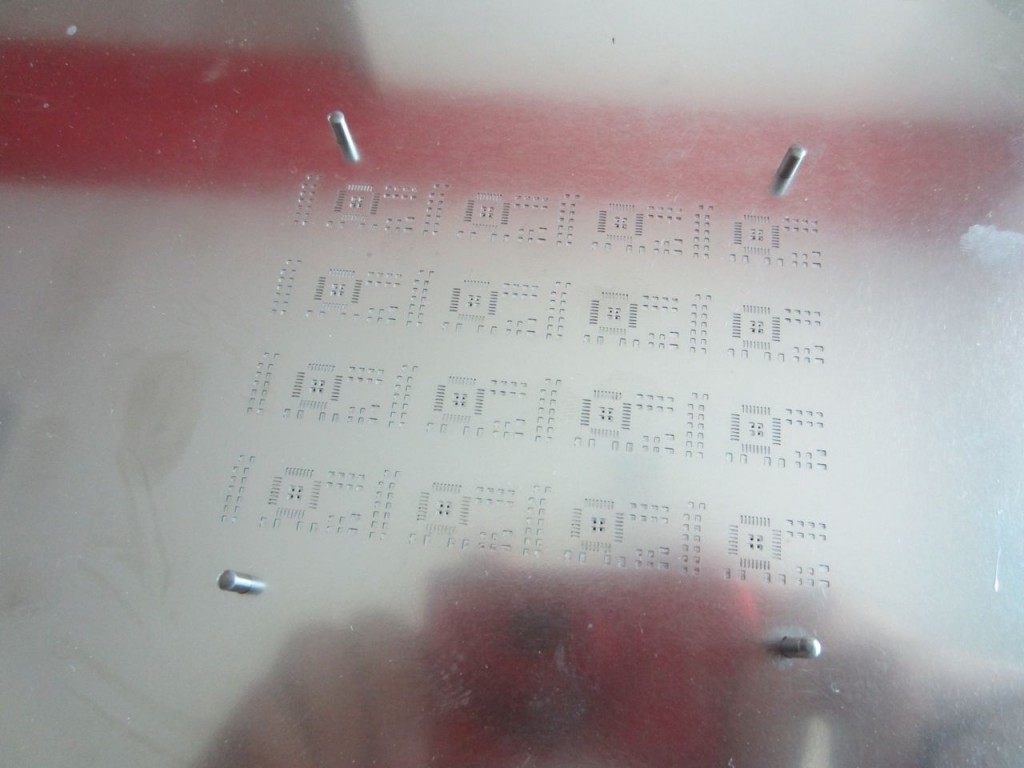
Using the same tooling pins, place your solder stencil onto the tooling block. Since the stencil is much bigger, it can be hard to get it aligned. I like to line up one hole first using light from above, then rotate the stencil around that pin until it slides over the rest of the pins. It should lay flat against the PCB when you are done.
The pins should align the PCB and solder paste stencil very precisely. You should not see any green soldermask, only the silver pads where solder paste needs to be deposited.
Step 4: Apply your solder paste
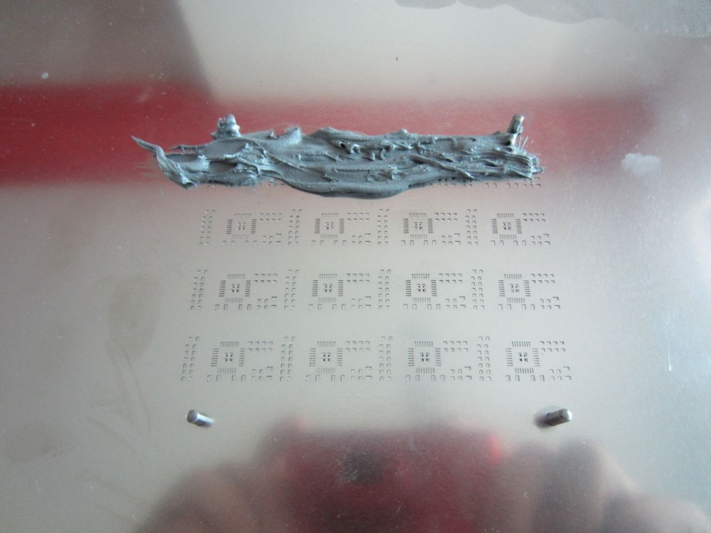
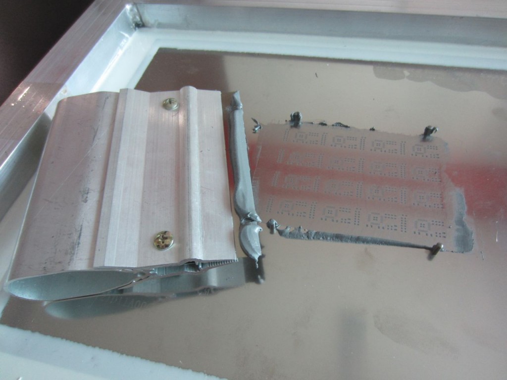
Applying the solder paste is easy and fast. Place a dollop of solder paste onto the stencil. Use your squeegee to apply it across the face of the stencil. Angle the squeegee in the direction you’re moving it, and make sure to apply the paste both forwards and backwards to get every little nook and cranny filled.
Apply a dollop:
Squeegee it across:
Step 5: Gently remove the stencil from the fixture
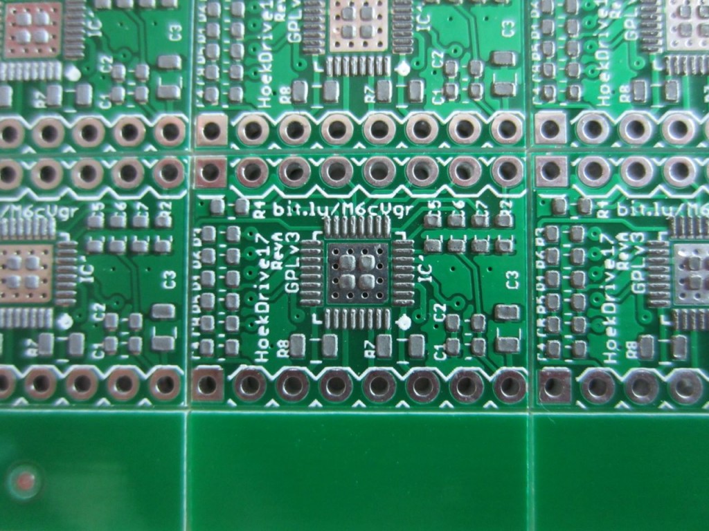
Once you’ve applied the solder paste, carefully remove your stencil. You should immediately clean the stencil off with isopropyl (rubbing alcohol) so that you can use it again later. You should end up with beautifully applied solder paste like the picture above. I highly recommend leaving the PCB on the fixture. This will give you a stable base to work on, and will prevent you from knocking the PCB onto the floor or something like that.
Step 6: Place SMT components using tweezers
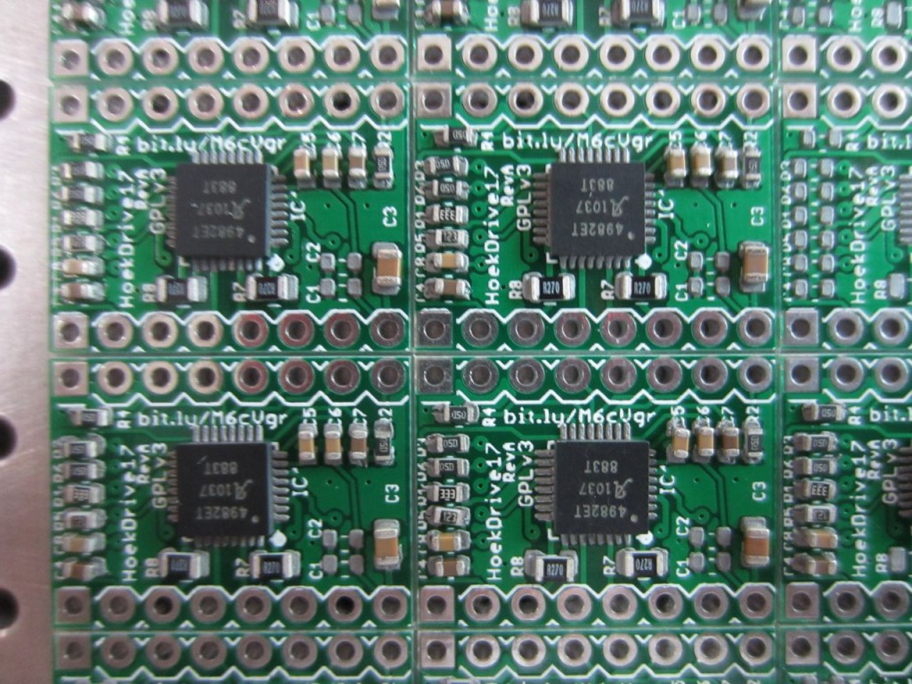
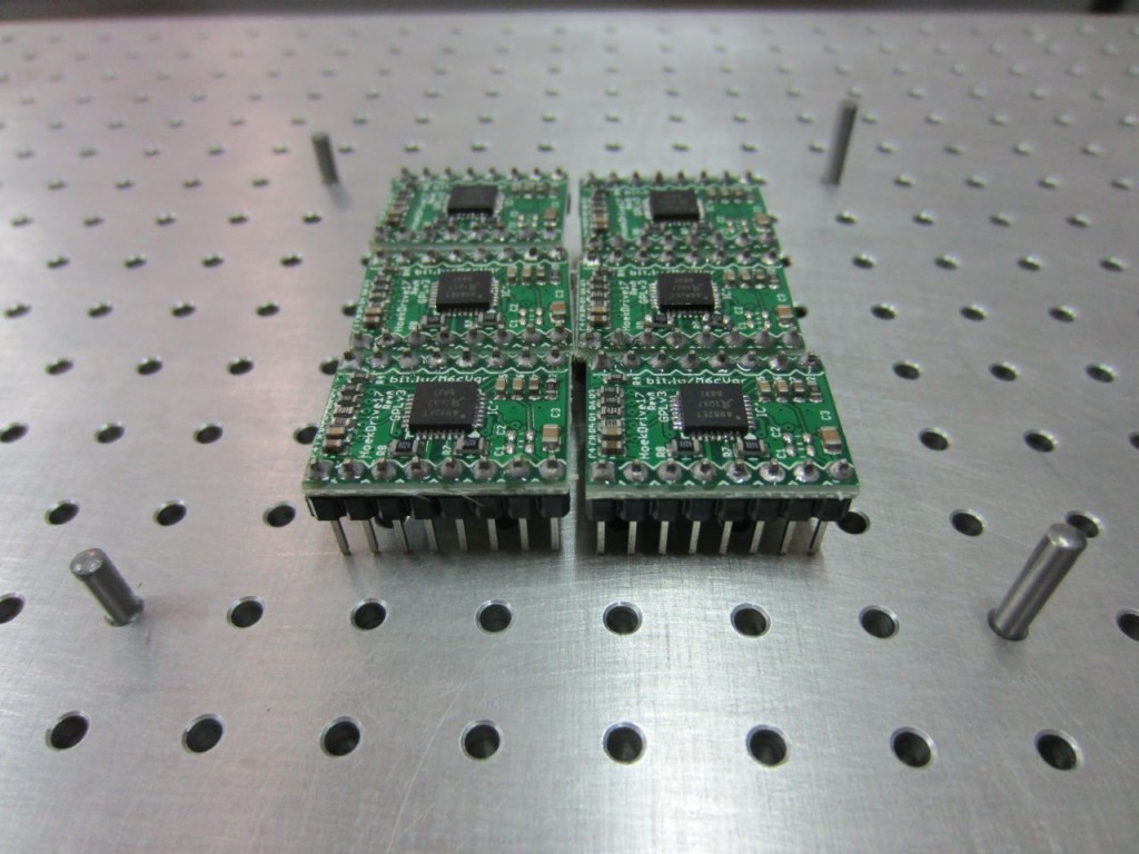
This is probably the trickiest part of the process. Use tweezers to pick and place each component onto the appropriate spot. A magnifying glass can help tremendously with this. Make sure you have good lighting and that you know what components go where. If you make a mistake you can dab a bit of solder on. Also, when the solder melts, it will self-correct to a small degree, so its okay if components are not exactly aligned. The boards in these pictures came out just fine, and you can see that the components are skewed a bit here and there.
Step 7: Reflow your board like usual
Use whatever process is convenient for you. I’m in love with this SMT oven here, but you may have your own preferred technique. If it works, go for it! Once the board has been soldered, it is a good idea to remove the flux using isopropyl alcohol and a toothbrush. Just don’t use it on your teeth afterwards!
Step 8: Solder your through-hole components (if any)
Using your trusty handheld soldering iron, solder in any through hole parts. If your board doesn’t have through hole parts, obviously skip this step.
Step 9: Test, test test!
Before using your board straightaway, test it! If you have a test fixture, then use that. If not, it is good to test for shorts between power/ground, as well as using a benchtop supply in current limiting mode set to a very low value and slowly ramp up the allowed current draw. If there is a short, this will allow you to catch it in a non-destructive way.
You’re done!
Using this technique you can solder very small parts that would otherwise be extremely difficult. I’ve successfully soldered 0402 components and QFN components with a 0.5mm pitch. You can easily do TQFP and any of the larger packages like 0603, 0805, and 1206.
If you have any feedback, leave it in the comments, or email me at zach at hoektronics dot com. Enjoy!
Pingback: Super Simple SMT: Stencil8 « adafruit industries blog
This is a great introduction. I wished I had this when I produced my first silk scren green sides. i tried to use t-shirt technology, and it was less-than-satisfactory. i didn’t have to deal with smt, but good ideas are good ideas.
Are those stepper drivers? A4988 compatible by any chance?
Great project by the way, thank you!
yes and yes. 🙂 github here: https://github.com/Hoektronics/Hoektron-CNC/tree/master/electronics/hoekdrive17
Pingback: MAKE | Zach Smith’s “Super Simple SMT: Stencil8″ Project
Pingback: Electronics-Lab.com Blog » Super Simple SMT: Stencil8
Hello. What PCB fab are you using?
http://www.hqpcb.com – chinese only so i’m not sure how much help it will be unless you live in china. alternative: move here? 😉
Pingback: Semi-professional board assembly for your workshop - Hack a Day
Thanks for the post Zach, I just caught this on Hackaday.
I know you said you live in Shenzhen, but could you comment on where we might be able to find that metal-blade squeegee? And what about that frame that you have the laser-cut stencil mounted in?
Mike
I blogged all my suppliers over at Haxlr8r: http://haxlr8r.com/blog/electronics-prototyping-in-shenzhen
both those things come from taobao.
Pingback: Semi-professional board assembly for your workshop | Cool Internet Projects
Hi Zach,
Nice post, thank you very much!
How much is this Tech168 T-962A oven?
Best Regards,
Alan
i got mine for about $200 at the shenzhen electronics market. i hear you can get them on ebay no problem.
I’ve been toying around with this stuff myself and after reading this I started looking around for cheaper stencils. I found this link (http://www.ebay.com/sch/i.html?_trksid=p5197.m570.l1313&_nkw=SMT+Stencil&_sacat=0&_from=R40) searching for “SMT Stencil” on ebay. They will manufacture a SMT stencil for $20. I’ve used Pololu in the past but I’ve found it a little expensive for the cheapo kapton sheets, while they work, don’t leave a lot f paste and a tend to move around a lot during application.
That stencil looks almost identical to the ones I use. I wouldn’t be surprised if they came from the same guys here in Shenzhen.
That oven has mixed reviews. Like underrated heating time/power. Are you happy with it?
so far so good. i have only done small boards so far though.
Great tutorial. Are the plate and pegs off-the shelf, or did you have to get them made? Could you suggest a supplier? Thank you
the pegs are off the shelf. i got mine on taobao, but these are the sorts of keywords i would use while searching: “precision steel pcb fixture pin dowel alignment tooling”
if you’re in the US, I bet mcmaster.com has them. they are 2.5mm diameter x 15.8mm length.
http://item.taobao.com/item.htm?id=19894820377
Best NOT to apply your solder paste as the step 4 picture.
Doing it this way can lead to excessive solder paste on the first row of boards, and makes the underside of the mask dirty.
Instead apply the paste just above the holes area about 1 Inch.
This will ensure you have a good ‘wave’ in front of your squeegee.
The paste then rolls over the holes excluding any trapped air.
good call. that was a bit sloppy on my part.
Thats the same oven as I use 🙂
Did you dind that the timng was accurate? I have had to create my own profiles that had compressed timings as 7 minutes as far as the oven timer was concerned was 10 minutes in real time…
Love the process though – Thanks.
I’ve seen a couple comments to that effect, but I hadn’t noticed it. I’ll definitely time it next set of boards.
Word of advice Zach you need more solder paste on the ground plane of your QFN device. A good rule of thumb is 60% but that device has a LOT of thermal vias so I would go up even more.
Thanks for the advice. Next batch I’ll bump it up. I just checked out tannlin.com… holy crap your laser machines look nice. Any spare ones laying around you want to send me? 😉
I can see to improvements for your system right off the top.
1) Add ridges to your hold down pins so that your board is held off the base the height necessary for your through hole parts. This will allow you to solder everything at the same time.
2) Since you have a metal laser cutter, create an additional template that allows you to drop your SMDs in place. This will allow for quicker placement of parts while at the same time assure even alignment and neatness. By having the plate half the thickness of the parts or set up off the board slightly, you should be able to remove the board without disturbing the parts. It may be possible to 3D print such a board.
Take care.
I mean two not to! 🙂
Hi Scott,
Could you explain your template idea a bit further – in terms of what exactly it comprises. I am having trouble visualizing how it would help with aligned SMD placement.
Best,
Anders
I received the following email from “Anders Johansson” asking me to further explain the template idea.
Email Start
I am really curious about this method now (since you state it helps
alignment/placement), and wanted to better understand what exactly the
method entails. When you say “template”, what are you talking about —
would it be like a stencil that is placed over the board, except only
for placement (and not for solder paste)? And how would that help with
the alignment exactly — Could you perhaps clarify just a bit further
please?
Email end
First off, I should have said stencil.
The stencil for parts placement would have holes large enough for the given part to drop through yet small enough so that the hole acts as a guide for the part, allowing it to be both properly aligned and put in it’s placed. The solder stencil could be easily modified to facilitate this.
The parts stencil could also contain labels that indicate which part goes into the given hole making placement faster and more efficient with multiple production scenarios.
After the parts are put in place, the stencil is carefully removed in the same manner that the solder stencil is removed. However, if the parts stencil is made of metal as the solder stencil is, and not touching the solder, it should be possible to leave it in place until the soldering process is completed thereby providing for that additional professional look.
As far as my first suggesting is concerned,
>>>
Add ridges to your hold down pin
>>>
This can be accomplished with full circular washer type spacers, or half round spacers that are placed on the pins prior to the stencil. Half round spacers would allow for ease of installation by raising the board after the solder stencil has been removed.
I hope this helps anyone with the same questions.
Scott A. Tovey
Thanks Scott. I think your suggestion of holding this second stencil with a slight vertical offset from the PCB is a good one to help prevent any messing with the solder paste. As far as I can see, the primary concern — in practice — will be to adjust the size of these cutouts to be JUST right, so as to be large enough to be easily removable without disturbing the parts, yet small enough to of course serve the original purpose of allowing the parts to fall exactly in place. Only one way to find out how helpful this will be — I’m going to try it out and see what happens.
Hey Zach,
Thanks for all the valuable info, worths gold to me! I’m in love with your method and planning to use it.
As for the reflow oven lately I was thinking about building one but I’d rather prefer buying a ready-made product and the Puhui T-962A seems to offer everything I need.
As for its price instead of $200 I could only see it seeling for about $400 + $200 shipping to Hungary.
Do you have any ideas where could I get it for (a lot) cheaper?
Thanks in advance!
I to can only find the T-962A for $350 + $150 postage….totalling 500 to Australia.
At $200 + $150 postage it would still be a instead buy.
I would suggest using a hot-plate. I did it for years and it really works well. 🙂
Thanks for the tip Zach but if I’ll go pro I won’t go pro halfway 🙂
As an unrelated issue could you please darken the text color of the comment fields? It’s so bright it’s almost invisible.
Pingback: Soldando placas BGAs em casa | Alan Carvalho de Assis
Great article, very helpful for my startup.
Are there any good industrial reflow hotplates you could recommend? Seems that most consumer hotplates don’t have uniform heating.
Also, do you know how the 962A oven works with plastic/metal connector parts like USB ports? Sparkfun had an article that indicated their reflow oven had a hard time with parts like these, but that hotplate worked perfect.
Thanks again!
Unfortunately I don’t really know any. I haven’t done USB connectors yet, but I’ll post if I have any issues.
Instead of the no name 962A I would rather go for the Atten AT-R1825 which sells in China for about RMB 1600. Atten is some kind of brand in China. They have 3 models, R1825 is the middle one.
Yeah, I tried to go for that too, but they were all sold out and I wanted one that day. 🙂
Well, after some research the T962A has a larger tray then the AT-R1825. I retract my previous comment and now support the T962A.
Can it do lead-free too? I guess ‘yes’… or?